Retaining wall design · Mount Gravatt East QLD
In short: The client needed drawings for concrete block retaining walls in Mount Gravatt East, with one length of wall beside an existing sewer. We designed reinforced, core-filled block walls scheduled from 800 mm to 2.8 m high, set that length's footing on 450 mm concrete piers taken below the sewer's zone of influence, and issued the set for approval.
- Service
- Retaining wall design
- Location
- Mount Gravatt East QLD
- Completed
- September 2026
- Walls
- Reinforced, core-filled concrete block (Besser block) retaining walls on reinforced concrete footings, for earth retaining only
- Wall heights in the schedules
- 800 mm to 2800 mm, in three height ranges
- Block series
- 150 series up to 1200 mm, 200 series from 1400 to 2000 mm, and a 300 series base under 200 series block from 2200 to 2800 mm
- Beside the sewer
- 450 mm diameter mass concrete piers (P1), 1000 mm minimum and at least 300 mm below the sewer's zone of influence, or to hard strata
- Design loads
- 10 kPa surcharge, 18 kN/m³ backfill, 150 kPa minimum allowable bearing capacity, and a slope behind the wall no steeper than 1 in 4
- Site class
- H2, as specified in the geotechnical report
- Blocks and core fill
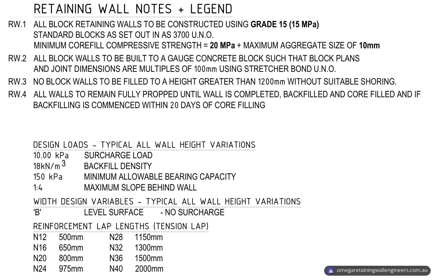
- Grade 15 (15 MPa) blocks as set out in AS 3700, core fill of at least 20 MPa with 10 mm maximum aggregate
- Drainage
- Granular fill the full height behind the wall, dimensioned nominally 300 mm behind 150 and 300 series block and 400 mm behind 200 series block, and a 100 mm ag drain in geofabric surrounded by free-draining gravel, falling to an outlet
- Main standards in the general notes
- AS 3600-2018 (concrete), AS 3700-2018 (masonry), NCC 2022 Volume Two
- Drawing set
- 8 sheets, first issued for approval and then revised twice in response to the client's comments
The brief
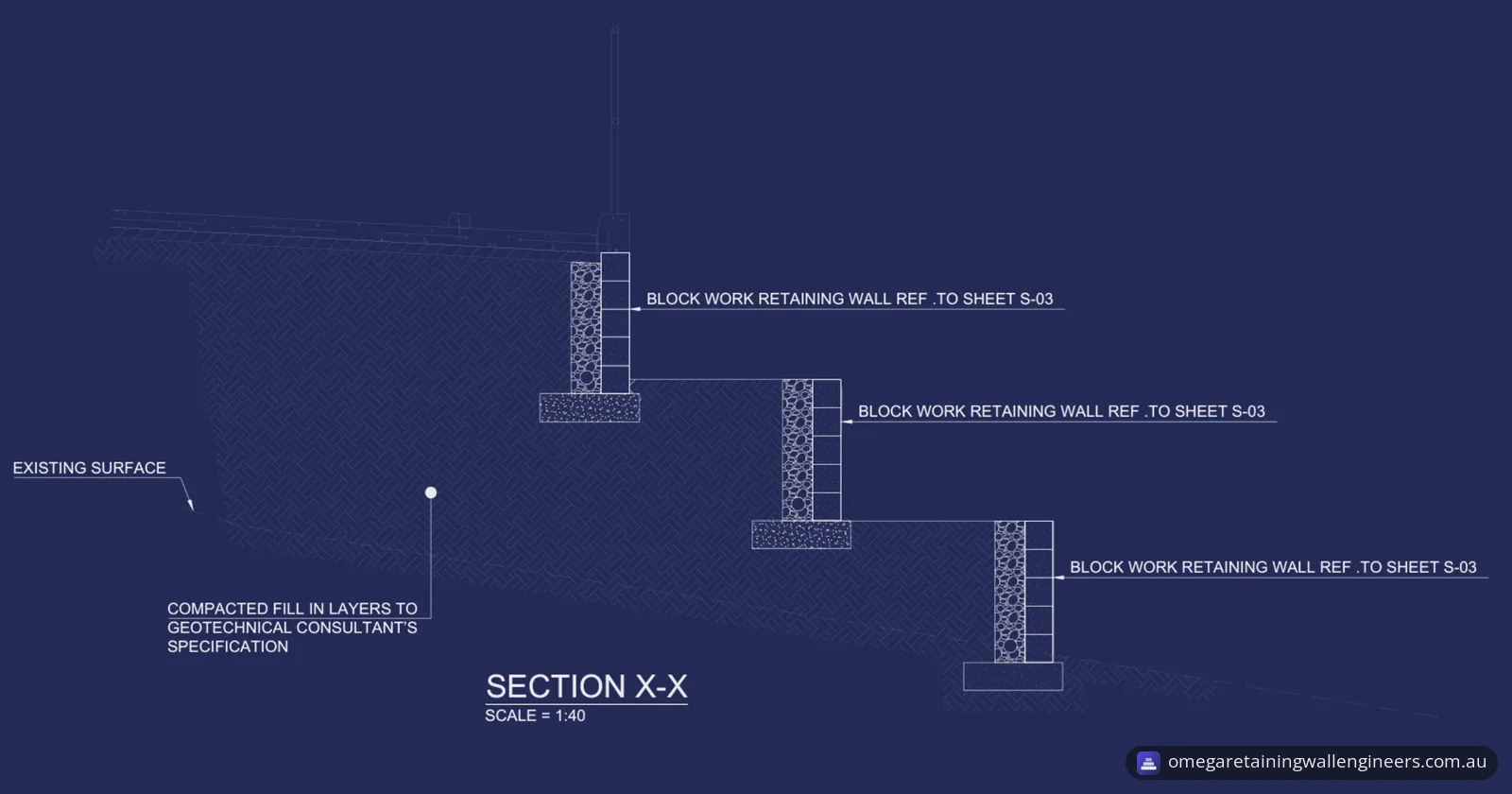
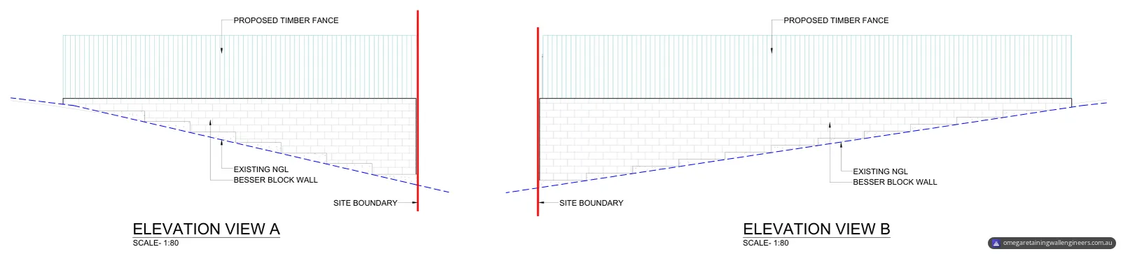
The client needed structural drawings for concrete block retaining walls on a site in Mount Gravatt East, in the City of Brisbane. The drawings show three lengths of wall. Elevations A and B show walls with a level top while the existing ground falls along them, with a proposed timber fence drawn above.
An existing sewer line runs beside one length of the wall. The layout plan marks the sewer's zone of influence along that length, and the wall's footing there is carried on concrete piers taken below it.
The drawing set first went out for approval and was then revised twice in response to the client's comments.
Why it needed a structural engineer
The wall schedules run from 800 mm up to 2800 mm high. Brisbane City Council says a retaining wall needs no building approval only if it meets every listed condition, including that the total height of the wall and the fill or cut it retains is no more than one metre above the wall's natural ground surface. Most of the heights in these schedules are above that one-metre figure. The general notes say the drawings are subject to approval by the relevant local authority before construction, and that no works may start until written authorisation to proceed has been issued.
The sewer adds a second set of rules. In Queensland, building work over or near sewers, water mains, stormwater drains and combined sanitary drains must be assessed against the Queensland Development Code MP 1.4 (Business Queensland, build over infrastructure). The FAQ below sets out when it applies to a retaining wall.
Our council approval and compliance page sets out what councils generally require and the documentation we prepare for approval.
What we designed
We designed reinforced, core-filled concrete block retaining walls on reinforced concrete footings, with a standard section and schedule for each height range. Concrete block walls are one of the retaining wall types we engineer.
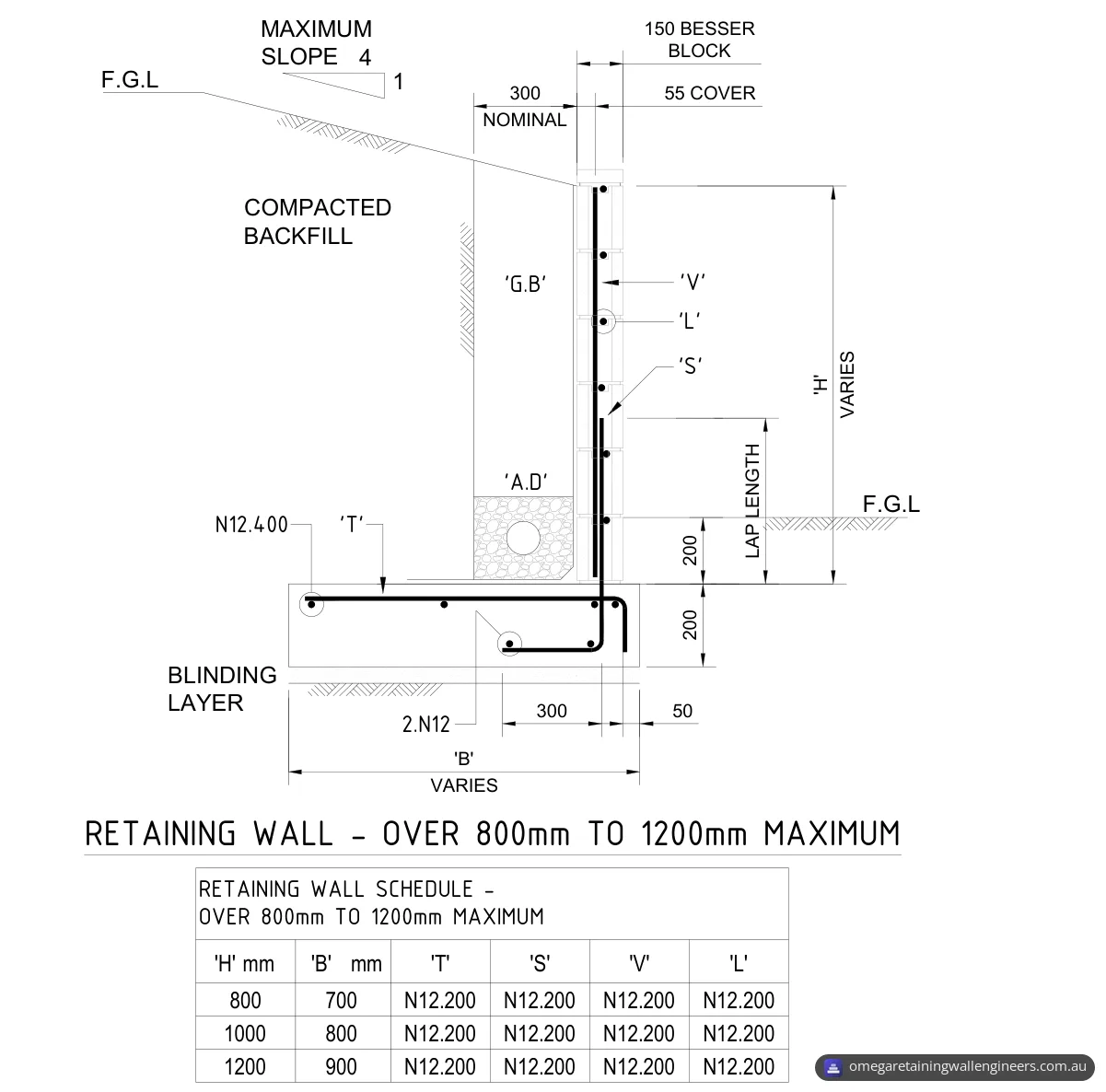
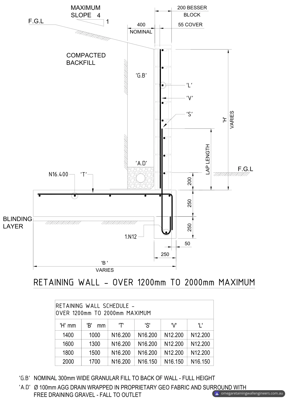
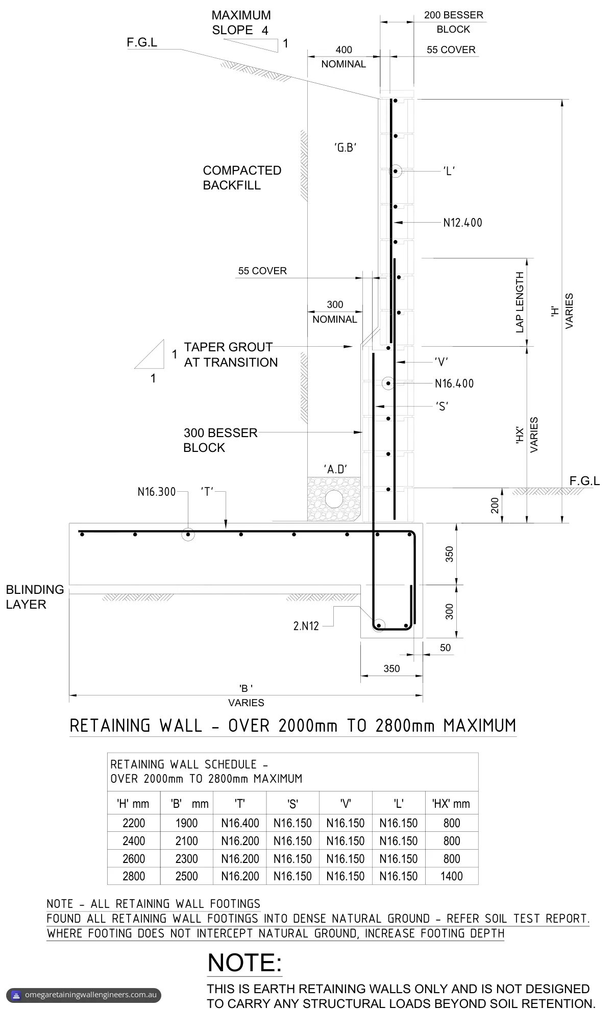
- Three height ranges. The section sheet covers walls over 800 mm and up to 1200 mm (150 series block), over 1200 mm and up to 2000 mm (200 series block), and over 2000 mm and up to 2800 mm (200 series block on a 300 series base).
- The tallest walls. For walls of 2200 to 2800 mm, the lower part of the wall (dimension 'HX') is 300 series block, 800 mm high, or 1400 mm for a 2800 mm wall. Above it is 200 series block, with the grout tapered at the transition.
- Footings. Each wall sits on a reinforced footing over a blinding layer, and the footing runs back under the backfill (width 'B' in the schedules). The top of the footing is 200 mm below finished ground level on the low side. The footing is 200 mm thick for walls up to 1200 mm. For walls over 1200 mm it is 250 mm thick, with a section 250 mm wide and 250 mm deeper under the wall. For the tallest walls these become 350 mm thick, 350 mm wide and 300 mm deeper.
- Reinforcement. The wall reinforcement has 55 mm cover. The schedules use N12 bars at 200 mm centres for all four scheduled bar marks ('T', 'S', 'V' and 'L') in walls up to 1200 mm, bring in N16 bars from 1400 mm, and use N16 bars at 150 mm centres for the 'S', 'V' and 'L' bars from 2000 mm. Tension lap lengths are 500 mm for N12 bars and 650 mm for N16 bars.
- Design loads. The notes list design loads for all wall heights: a 10 kPa surcharge, a backfill density of 18 kN/m³, a minimum allowable bearing capacity of 150 kPa and a slope behind the wall no steeper than 1 in 4.
- Blocks and core fill. The walls use Grade 15 (15 MPa) standard blocks as set out in AS 3700, with core fill of at least 20 MPa compressive strength and a maximum aggregate size of 10 mm. They are built to a gauge concrete block, so block plans and joint dimensions are multiples of 100 mm, in stretcher bond unless noted otherwise.
- Concrete. The general notes call for 32 MPa concrete to AS 3600-2018 unless noted otherwise. Any concrete in contact with aggressive or acid sulfate soils, groundwater or chemical attack is to use sulfate-resistant cement.
- Drainage. The drawings show granular fill the full height behind the wall, dimensioned nominally 300 mm behind 150 and 300 series block and 400 mm behind 200 series block, with a 100 mm ag drain wrapped in geofabric and surrounded by free-draining gravel, falling to an outlet. Our guide to retaining wall drainage design explains why drainage behind a wall matters.
- Earth retaining only. The notes state that these are earth-retaining walls only, not designed to carry any structural loads beyond soil retention.
- Building the walls. No block wall is to be filled to a height greater than 1200 mm without suitable shoring, and the notes set out when the walls must stay fully propped during core filling and backfilling.
- Detail sheets. Two sheets cover footing corners and steps, block wall corners and ends, control joints, and four methods for stepping the footings along a slope.
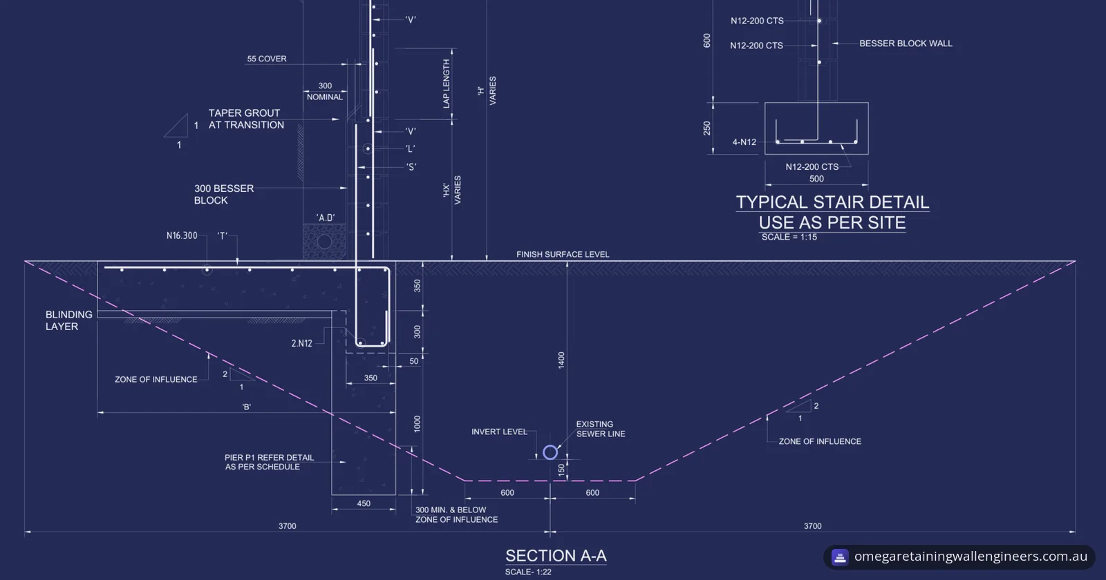
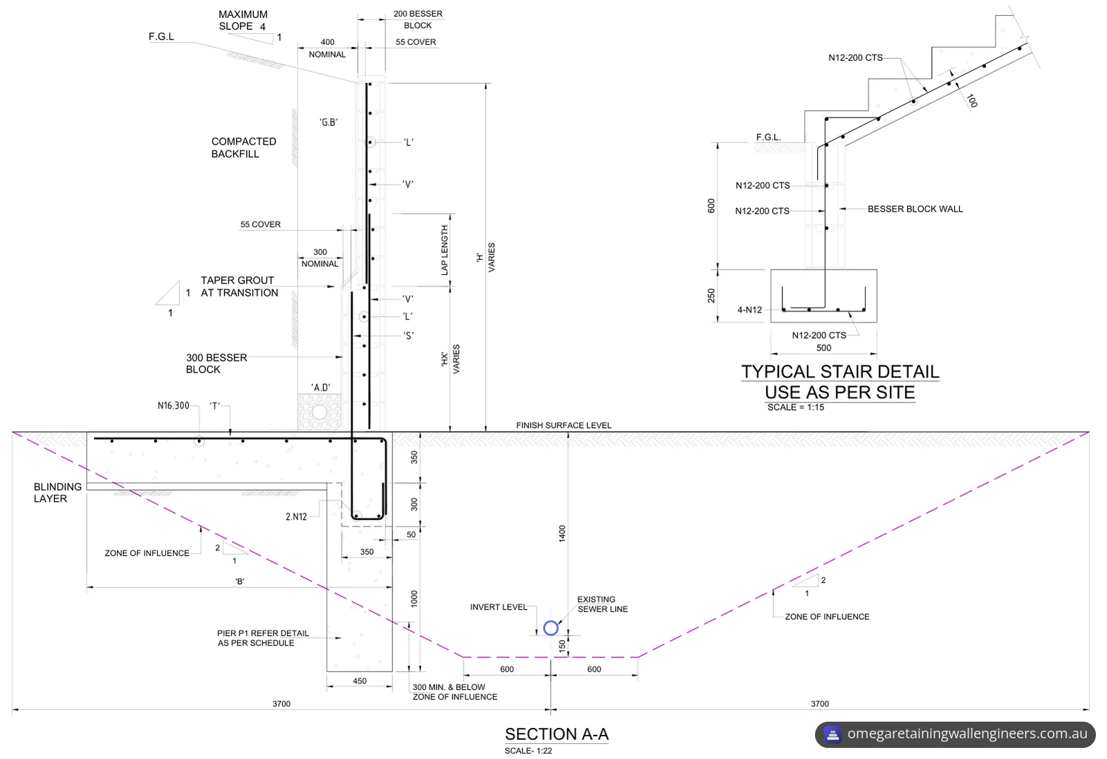
- Stairs. The Section A-A sheet also has a typical stair detail, to be used as the site requires. It shows a reinforced concrete stair on a 600 mm high block wall over a 500 mm wide, 250 mm deep footing.
The wall schedules:
| Wall height 'H' (mm) | Footing width 'B' (mm) | Block | 'T' | 'S' | 'V' | 'L' |
|---|---|---|---|---|---|---|
| 800 | 700 | 150 series | N12.200 | N12.200 | N12.200 | N12.200 |
| 1000 | 800 | 150 series | N12.200 | N12.200 | N12.200 | N12.200 |
| 1200 | 900 | 150 series | N12.200 | N12.200 | N12.200 | N12.200 |
| 1400 | 1000 | 200 series | N16.200 | N16.200 | N12.200 | N12.200 |
| 1600 | 1300 | 200 series | N16.200 | N16.200 | N12.200 | N12.200 |
| 1800 | 1500 | 200 series | N16.200 | N16.200 | N12.200 | N12.200 |
| 2000 | 1700 | 200 series | N16.200 | N16.150 | N16.150 | N16.150 |
| 2200 | 1900 | 300 series base ('HX' 800 mm), 200 series above | N16.400 | N16.150 | N16.150 | N16.150 |
| 2400 | 2100 | 300 series base ('HX' 800 mm), 200 series above | N16.200 | N16.150 | N16.150 | N16.150 |
| 2600 | 2300 | 300 series base ('HX' 800 mm), 200 series above | N16.200 | N16.150 | N16.150 | N16.150 |
| 2800 | 2500 | 300 series base ('HX' 1400 mm), 200 series above | N16.200 | N16.150 | N16.150 | N16.150 |
'T', 'S', 'V' and 'L' are the bar marks on the wall sections, each given as bar size and spacing in millimetres.
How the design handles the sewer
The layout plan marks the existing sewer line, its zone of influence and a zone of influence area along one length of wall, with P1 piers spaced along that length. Section A-A shows how the wall and the sewer relate.
- The zone of influence. On Section A-A, the zone starts 150 mm below the invert of the sewer pipe and extends 600 mm either side of the pipe's centreline. From there its sides slope up to meet the finished surface 3.7 m either side of the centreline.
- The wall at the sewer. Section A-A draws the wall with the same build-up as the tallest range: a 300 series block base with 200 series block above, on a footing that runs back under the backfill.
- The piers. A 450 mm diameter mass concrete pier sits under the deeper section of the footing beneath the wall. The pier schedule gives its depth as 1000 mm minimum and 300 mm minimum below the zone of influence, or to hard strata. Section A-A shows the base of the pier at least 300 mm below the zone of influence line.
What has to be confirmed on site
The design depends on the ground, so the drawings list what the builder and the client must check:
- Site class. The foundation design is based on site class H2, as specified in the geotechnical report.
- Founding. All retaining wall footings are founded into dense natural ground, and where a footing does not reach natural ground, its depth is increased. Whatever depth is designed or specified, footings are to be extended as required into stiff natural soil.
- Varying ground. Ground conditions can vary significantly over a short distance, so the founding depths of footings and piers are to vary to suit them.
- Geotechnical input. The general notes ask the client or their representative to engage a geotechnical consultant to evaluate and verify the foundation soil conditions before construction starts. Our soil testing and geotechnical coordination page explains how ground conditions feed into a wall design.
- Groundwater. If groundwater is found at the design depth of the footings or piers, the engineer must be contacted immediately.
- Dimensions. The builder confirms all dimensions, existing conditions, obstructions and limitations on site before ordering or delivering any material, and reports any discrepancies to the engineer.
- Inspections. The general notes ask for required inspections to be confirmed 72 hours in advance.
The result
The client received the 8-sheet structural set for the retaining walls, issued for approval and revised twice to take in their comments. Once approved, it gives the builder the block series, footing width and reinforcement for each scheduled wall height, the drainage behind the walls, the pier detail where the wall runs beside the sewer, and the ground checks to make before and during excavation.
Planning a retaining wall near a sewer?
Our retaining wall design and engineering certification service covers the structural design, footing and reinforcement details, drainage and backfill requirements, and drawings for approval. Send us a site plan or survey, photos of the area, the heights you need to retain, where any sewer or stormwater lines run, and any geotechnical report you have. Our Brisbane page lists the South East Queensland areas we cover, including Brisbane South. You can request a quote online or call 07 2146 4066.
Photos and drawings
From the report
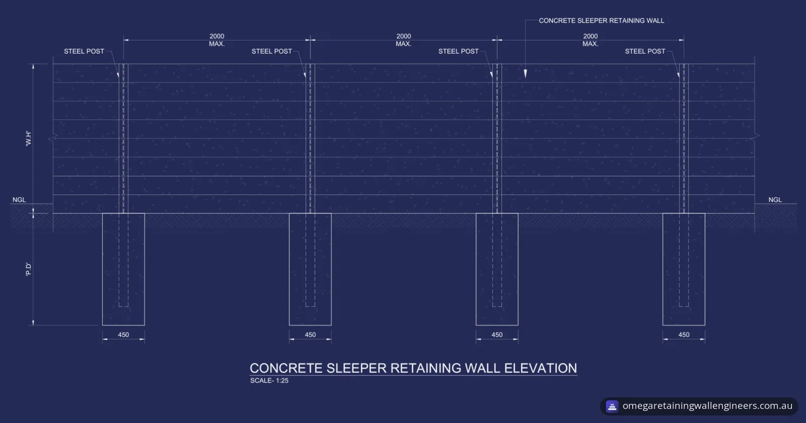
Sample pages from what the client received (personal details removed).
Frequently asked questions
Does a retaining wall need building approval in Brisbane?
Not always. Brisbane City Council says you don't need building approval for a retaining wall if there's no surcharge loading over the wall's zone of influence, the total height of the wall and the fill or cut it retains is no more than one metre above the wall's natural ground surface, the wall is no closer than 1.5 metres to a building or another retaining wall, and it doesn't form part of the fencing for a pool. If the wall doesn't meet those requirements, you need building approval, which you organise through a licensed building certifier.
Does a retaining wall need planning approval in Brisbane?
Brisbane City Council says you generally don't need planning approval if the wall supports filling or excavation of less than one metre. You may need it if the site is covered by an overlay such as the flood, landslide, heritage or bushfire overlay codes, if the wall is associated with a subdivision or a material change of use, or if the filling or excavation exceeds the thresholds in the Filling and excavation code. Council suggests checking your property's zones and overlays in City Plan online first.
What rules apply to building near a sewer in Queensland?
Business Queensland says building work over or near sewers, water mains, stormwater drains and combined sanitary drains must be assessed against the Queensland Development Code MP 1.4. It does not apply to accepted (self-assessable) building work for a structure such as a retaining wall, unless the structure is supported by a strip footing, or to work beyond a specified minimum distance from the infrastructure. Where the work doesn't comply with an acceptable solution, the application must be referred to the relevant service provider, which for a sewer is the sewerage service provider. It has 20 business days to assess the application and may charge a fee.