Retaining wall design · Kariong NSW
In short: The client was replacing a retaining wall in Kariong NSW and needed structural drawings for the new one. We designed a concrete sleeper wall up to 1200 mm high, with steel posts in 450 mm concrete piers, a pier and post schedule for each wall height, and drainage behind the wall, in a five-sheet set issued for approval.
- Service
- Retaining wall design
- Location
- Kariong NSW
- Completed
- September 2026
- Wall type
- Precast concrete sleepers stacked between steel posts, each post set in its own concrete pier
- Wall size
- Up to 1200 mm high, with the length set to suit site conditions
- Scheduled wall heights
- 600, 800, 1000 and 1200 mm, for stiff natural soils and a wall with no fence
- Piers
- 450 mm diameter in 25 MPa concrete, 1000 to 1350 mm deep depending on wall height
- Posts
- 100 UC 14.8 intermediate posts and 100 PFC end-of-wall posts, at most 2030 mm apart in the schedule and 2000 mm on the layout plan and elevation
- Sleepers
- 200 mm deep x 75 mm wide, typically 2000 mm long, 40 MPa concrete vibrated in steel forms, with two N12 bars and 30 mm cover
- Soil class designed for
- Class M (presumed, to be confirmed by the contractor before excavation)
- Founding
- At least 200 mm into natural silty clay with a verified allowable bearing capacity of at least 100 kPa (detail sheet). The layout plan asks for footings to be extended as needed into stiff natural soil or rock of at least 150 kPa, confirmed by the builder on site.
- Drainage
- Crushed rock fill at least 300 mm wide with a full-height geotextile layer, a 100 mm ag drain at a fall of at least 1 in 100, and an impermeable spoon drain
- Designed for
- Retaining soil only, with no structural loads beyond soil retention
- Main standards in the general notes
- AS 3600-2018 (concrete), AS 4100-2020 (steel), NCC 2022 Volume Two
- Drawing set
- Five sheets, issued for approval
The brief
The client was replacing a retaining wall at their property in Kariong, on the NSW Central Coast, and needed structural drawings for the new wall. The new wall is a concrete sleeper retaining wall: precast concrete sleepers stacked between steel posts, with each post set in its own concrete pier.
The wall is up to 1200 mm high, and its length is set to suit site conditions. The drawings had to show the builder how to found, build and drain the wall, and they were issued for approval.
Why it needed a structural engineer
At up to 1200 mm high, this wall is above the 600 mm figure in the NSW complying development rules, and above both heights at which Central Coast Council's planning controls call for a professional engineer's design.
- NSW planning rules. In NSW, a retaining wall needs no planning approval only if it meets every exempt development standard in the State's Codes SEPP. The NSW Department of Planning's page on earthworks, retaining walls and structural supports lists the main standards and says all works must be structurally adequate and comply with the Building Code of Australia. The NSW Planning Portal says earthworks and structural supports more than 600 mm above or below ground level may be done as complying development, under the development standards in Schedule 9 of the Codes SEPP.
- Central Coast Council. Kariong is in the Central Coast Council area. Chapter 2.1 of Council's Development Control Plan 2022 says retaining walls more than 600 mm above or below existing ground level within 1 m of any boundary, or more than 1 m above or below it anywhere else, must be designed by a professional engineer. This wall is above both heights.
- The building code. The Building Code of Australia is Volumes One and Two of the National Construction Code (NCC). NCC 2022 Volume Two, clause A6G11 classifies a retaining wall as a Class 10b structure, a non-habitable building or structure.
Requirements differ by state and council. Our council approval and compliance page sets out what is generally required.
What we designed
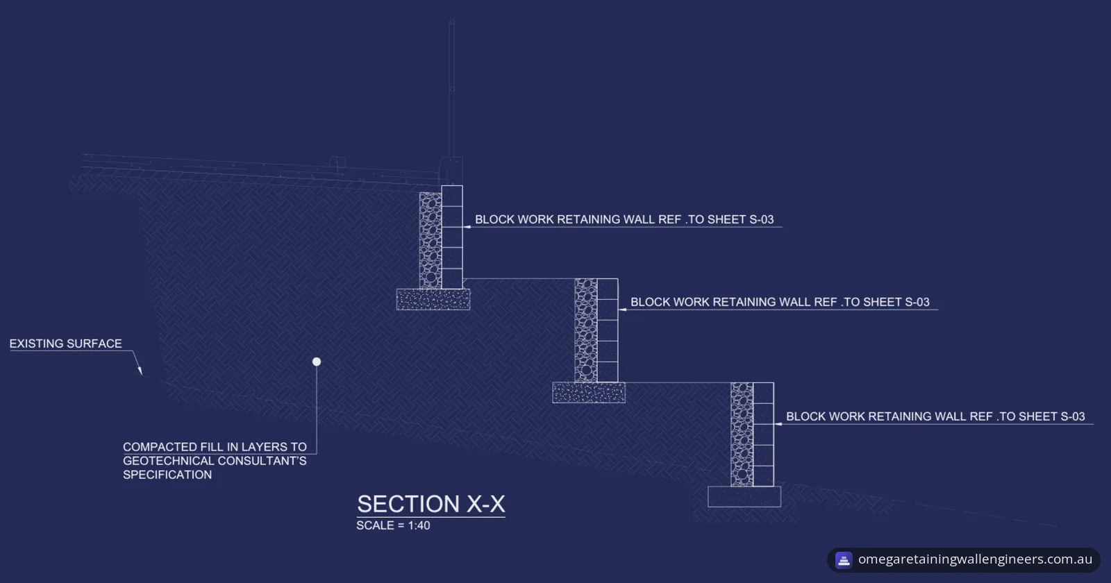
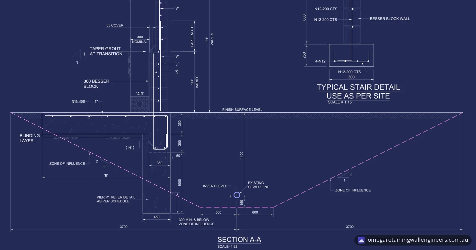
The drawing set has five sheets: a cover sheet, general notes, a retaining wall layout plan, the concrete sleeper wall details and a typical elevation.
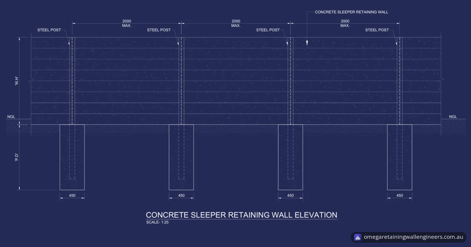
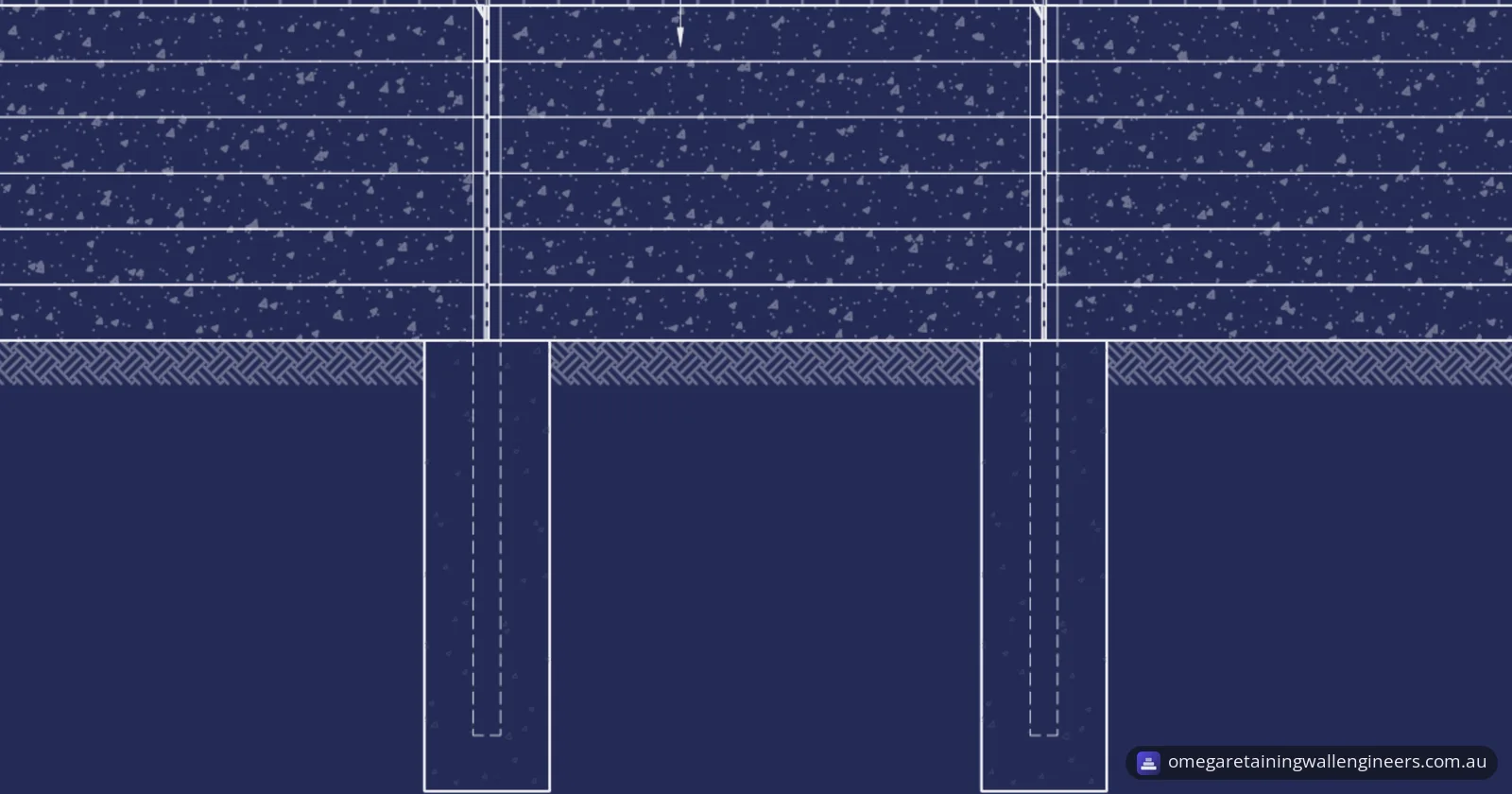
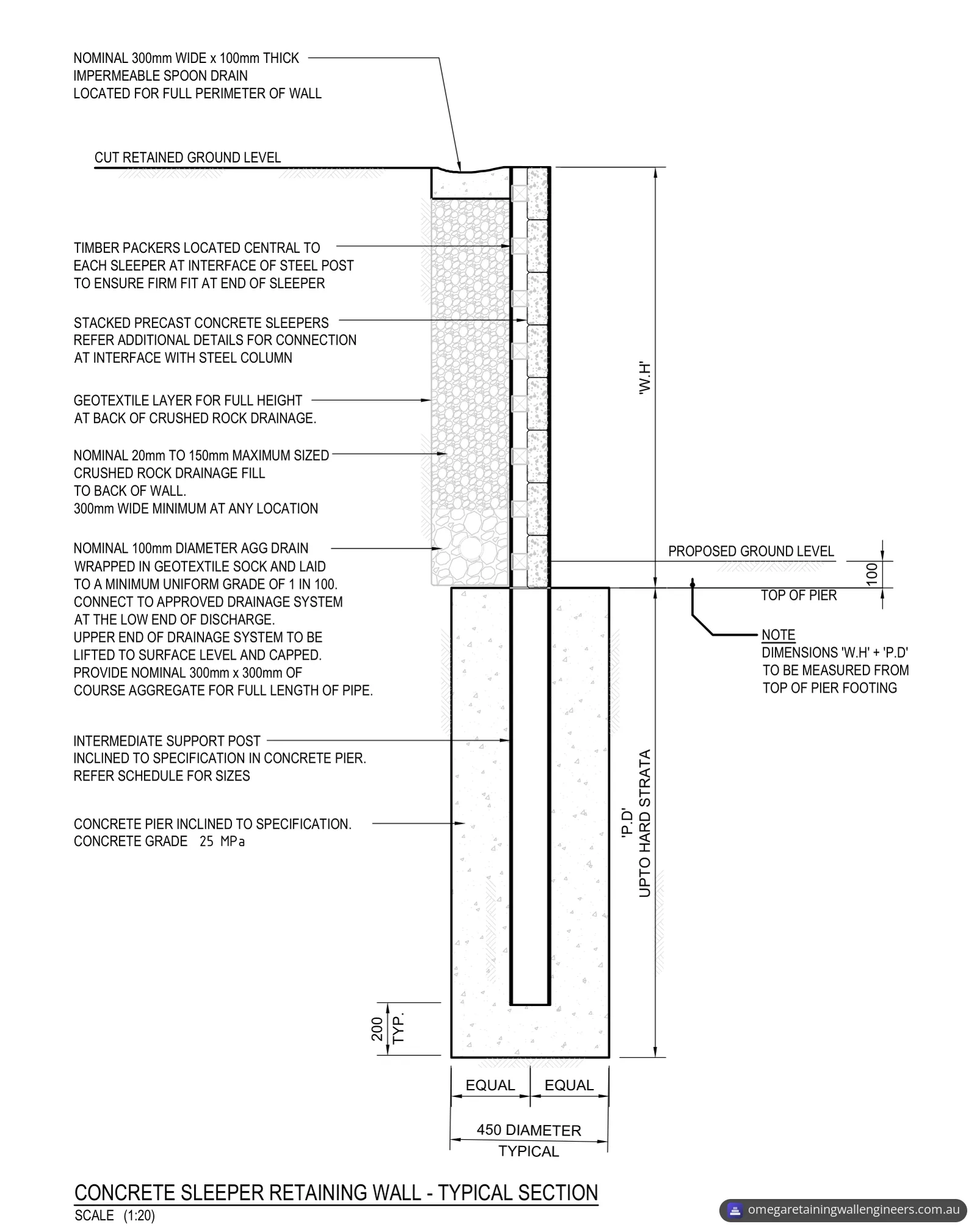
- Wall build-up. Precast concrete sleepers stack between steel posts. Timber packers sit centrally on each sleeper where it meets a post, so every sleeper end fits firmly.
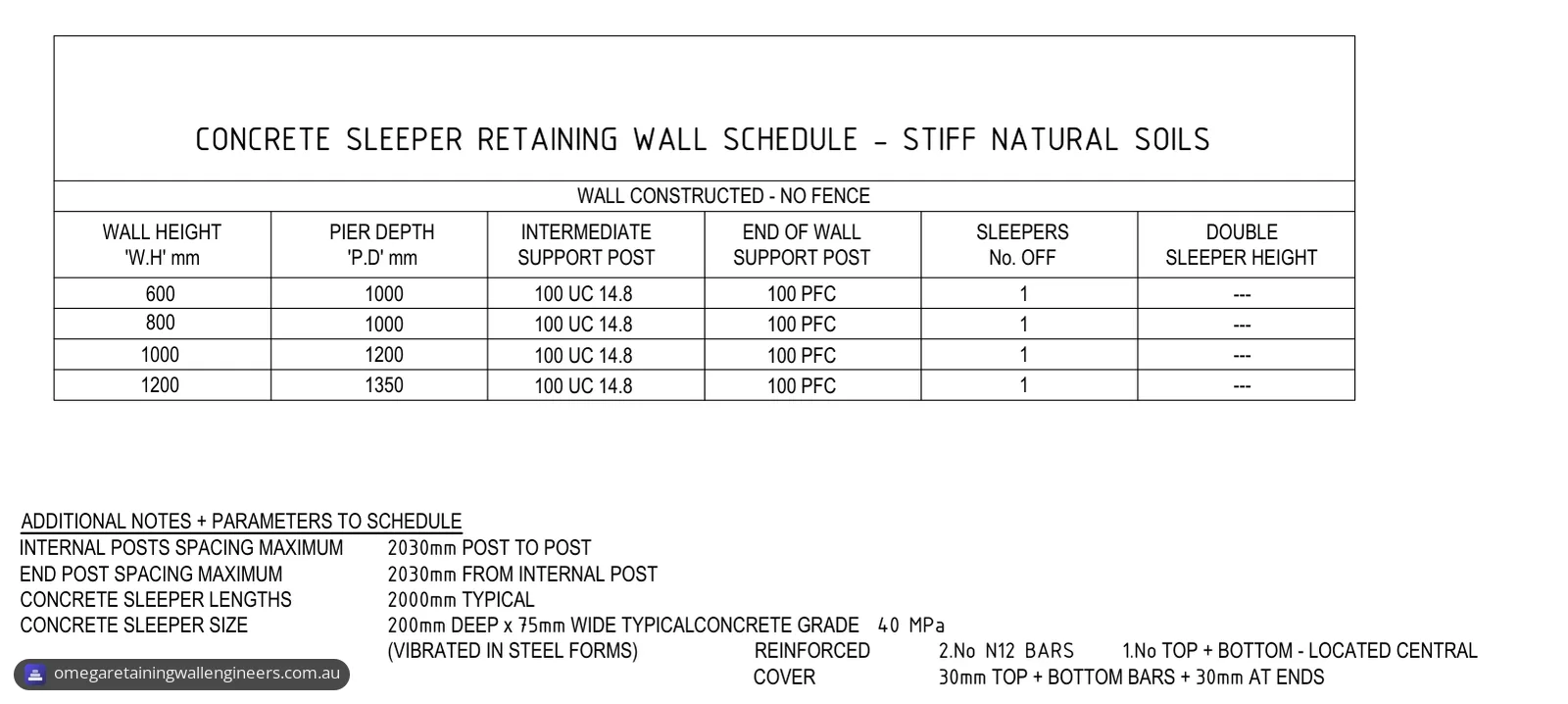
- Sleepers. The sleepers are 200 mm deep, 75 mm wide and typically 2000 mm long, in 40 MPa concrete vibrated in steel forms. Each has two N12 bars, one top and one bottom, located centrally, with 30 mm cover to the bars and 30 mm at the ends.
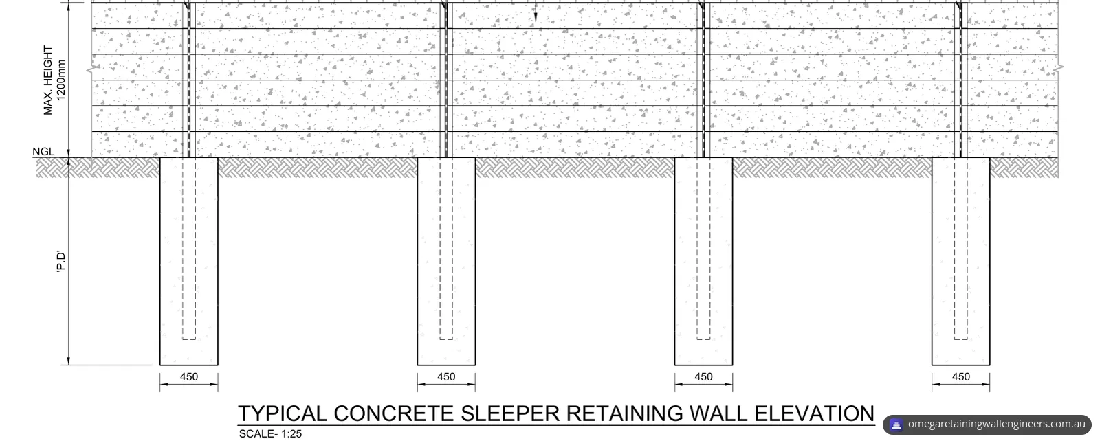
- Posts. Intermediate posts are 100 UC 14.8 sections and end-of-wall posts are 100 PFC sections at every scheduled height. The schedule allows up to 2030 mm between posts, and the layout plan and elevation show the posts at 2000 mm maximum.
- Piers. Each post is set in a 450 mm diameter pier of 25 MPa concrete. The top of the pier sits 100 mm below the proposed ground level, and the wall height and pier depth are both measured from it. The post stops 200 mm short of the base of the pier.
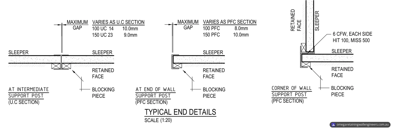
- Sleeper ends. The sleeper ends slot into the UC section at intermediate posts and into a PFC section at wall ends and corners, with blocking pieces on the retained face. The end details set a maximum gap for each section size.
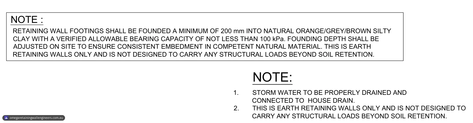
- Soil only. The wall retains earth only. It is not designed to carry any structural loads beyond soil retention.
The schedule, for stiff natural soils and a wall constructed with no fence, sets the pier depth and post sizes for each wall height, and lists no double-sleeper height for any of them:
| Wall height (W.H) | Pier depth (P.D) | Intermediate post | End-of-wall post |
|---|---|---|---|
| 600 mm | 1000 mm | 100 UC 14.8 | 100 PFC |
| 800 mm | 1000 mm | 100 UC 14.8 | 100 PFC |
| 1000 mm | 1200 mm | 100 UC 14.8 | 100 PFC |
| 1200 mm | 1350 mm | 100 UC 14.8 | 100 PFC |
Drainage behind the wall
- Drainage fill. Crushed rock, nominally 20 to 150 mm in size, fills the space behind the sleepers, at least 300 mm wide at any point.
- Geotextile. A geotextile layer runs the full height of the wall at the back of the crushed rock.
- Ag drain. A nominal 100 mm diameter ag drain, wrapped in a geotextile sock and bedded in a nominal 300 x 300 mm band of coarse aggregate along its full length, is laid to a uniform fall of at least 1 in 100.
- Outlet. The low end of the ag drain connects to an approved drainage system. Its upper end is brought up to the surface and capped.
- Spoon drain. A nominal 300 mm wide, 100 mm thick impermeable spoon drain runs the full perimeter of the wall at the top of the retained ground.
- Stormwater. Stormwater is to be properly drained and connected to the house drain.
Our guide to retaining wall drainage design explains what the ag drain, the free-draining gravel and the geotextile filter each do.
What has to be confirmed on site
The design depends on the ground, so the drawings list what the builder and the client must check:
- Soil class. The foundation is designed for a presumed Class M soil classification. The contractor should confirm it before excavation, and the design will be revised if actual site conditions differ.
- Founding. The footings go at least 200 mm into natural orange, grey or brown silty clay with a verified allowable bearing capacity of at least 100 kPa, as set by the note on the detail sheet. The founding depth is adjusted on site so the piers sit consistently in competent natural material.
- Ground variation. Ground conditions can vary significantly over a short distance, so pier depths vary with them. Whatever depth is specified, the footings are extended as needed into stiff natural soil or rock with an allowable bearing capacity of at least 150 kPa, confirmed by the builder on site.
- Geotechnical check. The general notes ask the client or their representative to engage a geotechnical consultant to evaluate and verify the foundation soil conditions before construction starts. Our soil testing and geotechnical coordination service can arrange this.
- Dimensions. The builder confirms all dimensions, existing conditions, obstructions and limitations before ordering or delivering any material, and reports any discrepancies to the engineer.
The result
The client received a five-sheet drawing set for the replacement wall, issued for approval. It gives the pier depth and post sizes for each wall height from 600 to 1200 mm, the sleeper specification, the sleeper end details at posts and corners, and the drainage behind the wall. Under the general notes, the plans stamped and approved by the building surveyor or relevant authority are the ones used for construction.
Replacing a retaining wall on the Central Coast?
Our retaining wall repair and replacement engineering includes full replacement designs, and our retaining wall design and engineering certification service provides engineering drawings for approval. Concrete sleeper walls are one of the retaining wall types we engineer, and we design walls for sites across the Central Coast. Send us photos of the existing wall, the heights you need to retain, any survey or site plan you have, and a soil or geotechnical report if there is one. You can request a quote online or call 07 2146 4066.
Photos and drawings
From the report
Sample pages from what the client received (personal details removed).
Frequently asked questions
Do I need approval to build a retaining wall in NSW?
Not if the wall meets every exempt development standard in the State's Codes SEPP. The NSW Department of Planning lists standards such as being at least 2 m horizontally from any other retaining wall on the site, at least 40 m from a body of natural water, and not redirecting the flow of any surface or ground water, or causing sediment to be transported onto an adjoining property. The works must also be structurally adequate and comply with the Building Code of Australia.
Can a retaining wall over 600 mm be complying development in NSW?
It can be. The NSW Planning Portal says earthworks and structural supports more than 600 mm above or below ground level may be done as complying development, under the standards in Schedule 9 of the Codes SEPP. Central Coast Council says a complying development certificate can be granted by Council or a private certifier, that some properties are restricted from complying development, and that a project that is neither exempt nor complying needs a development application.
When does Central Coast Council require an engineer to design a retaining wall?
Chapter 2.1 of the Central Coast Development Control Plan 2022 says a retaining wall more than 600 mm above or below existing ground level within 1 m of any boundary, or more than 1 m above or below existing ground level anywhere else, must be designed by a professional engineer. The height is measured from the base of the wall to its uppermost portion.